Introduction
Community Wireless Networks can be designed in many ways. To help you understand these different methods for designing networks, this document covers the basics of what different devices do in wireless networks, and how they can be used in different configurations. Using the knowledge and activities in this document, you can work with others to design the wireless network that works best for your community.
Reading and working through Learn Wireless Basics before this document will help you with some of the concepts used in designing wireless networks. It provides some necessary background information for this document.
Reading through this material should take about 30 to 45 minutes. Working through the activities, or diving deeper into the subject with a group may take longer.
Wireless Device Roles
There are three major “modes” a Wi-Fi device can use. These modes define the role a Wi-Fi device has in the network, and networks must be built out of combinations of devices operating in these different modes. How the devices are configured depends on the types of connections you want to use between parts of the network.
In discussing these modes and the examples below, several types of devices are used. In addition to the phones, tablets, and laptops you use in accessing a network, routers make up the hardware that runs the network. These routers are defined in Learn Networking Basics, but for the sake of this document the quick definition of a router is a network device that can connect one network to another, determine what traffic can pass between them, and perform other functions on a network, such as assigning IP addresses.
The three wireless roles are:
![]() Wireless Clients (Station)
Wireless Clients (Station)
![]() Devices such as computers, tablets, and phones are common Clients on a network. When you are accessing a wireless hotspot, or the router in your home or office, your device is the client. This client mode is also known as “station mode” as well.
Devices such as computers, tablets, and phones are common Clients on a network. When you are accessing a wireless hotspot, or the router in your home or office, your device is the client. This client mode is also known as “station mode” as well.
Some routers can operate as Clients as well, which allows them to act like the wireless card in a computer, and connect to other Access Points. This can bridge two Ethernet networks, or connect to more distant APs.
A Wireless Client is similar to a person in the audience of a play or movie. They are one of several or many people accessing information through the same conduit - someone speaking.
![]() Access Points (Master)
Access Points (Master)
![]() Most wireless networks are made using Access Points - devices that host and control the wireless connection for laptops, tablets, or smart phones. If you use Wi-Fi in your home or office, it is most likely through an Access Point. When a router is set up as an AP, it is said to be in “Master” or “Infrastructure” mode.
Most wireless networks are made using Access Points - devices that host and control the wireless connection for laptops, tablets, or smart phones. If you use Wi-Fi in your home or office, it is most likely through an Access Point. When a router is set up as an AP, it is said to be in “Master” or “Infrastructure” mode.
An AP is sometimes a stand-alone device that bridges between a wireless and wired (Ethernet) network, or is part of a router. APs can cover a range of areas with a wireless signal, depending on the power of the device and the type of antenna. There are also some APs that are weatherproof, designed to be mounted outdoors.
An Access Point is similar to a person on stage, addressing an audience or crowd - they are providing the information for everyone else. Those audience members can ask questions of the person on the stage, and receive a response.
![]() Ad-Hoc Node (Mesh)
Ad-Hoc Node (Mesh)
![]() Some wireless devices (laptops, smart phones, or wireless routers) support a mode called Ad-Hoc. This allows those devices to connect together directly, without an Access Point in-between controlling the connection. This forms a different type of network - in Ad-Hoc mode, all devices are responsible for sending and receiving messages to the other devices - without anything else in between. In an Ad-Hoc network, every device must be in this role, and using the same configuration to participate. Not all devices use this mode, and some have it as a “hidden” feature.
Some wireless devices (laptops, smart phones, or wireless routers) support a mode called Ad-Hoc. This allows those devices to connect together directly, without an Access Point in-between controlling the connection. This forms a different type of network - in Ad-Hoc mode, all devices are responsible for sending and receiving messages to the other devices - without anything else in between. In an Ad-Hoc network, every device must be in this role, and using the same configuration to participate. Not all devices use this mode, and some have it as a “hidden” feature.
Ad-Hoc devices are used to create a Mesh network, so when they are in this mode, they are called “Mesh Nodes”.
An Ad-Hoc or Mesh node is similar to an individual in a group or roundtable discussion. They can take equal part in the conversation, raising their hand when they want to speak so the others will listen. If someone at the end of the table cannot hear, one of the individuals in-between can repeat the original message for the listener.
Quick Activity: Describe the differences in the two example networks below. What are the roles and relationships between the different colored nodes in the networks?
Example 1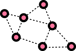
|
Example 2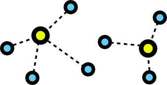
|
| Role of the Pink Nodes:
_______________________________ Relationship between nodes: _______________________________ |
Role of the Yellow nodes:
_______________________________ Role of the Blue nodes: _______________________________ Relationship between nodes: _______________________________ |
The two networks above are Ad-Hoc and Infrastructure (Access Point) networks. Are there places or times in a social situation where you are in an Access Point or Client situation? Are there places or times when you are in an Ad-Hoc situation?
What connects to what?
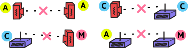
From the roles above, you can see that Clients always need to connect to an Access Point, and Mesh nodes all connect to each other. It should also be noted that due to how Wi-Fi is designed, this also prevents different roles from connecting to each other as well.
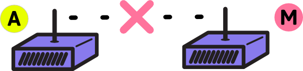
Access Points cannot connect to each other wirelessly:
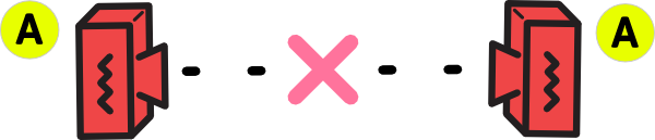
Clients cannot connect to each other wirelessly:
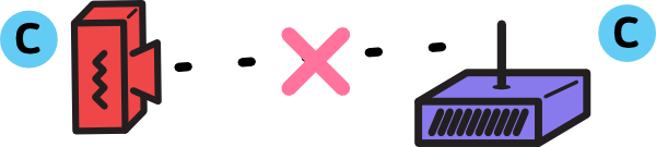
Clients cannot connect to Ad-Hoc (Mesh) devices wirelessly:
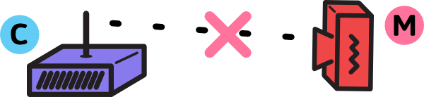
Access Points cannot connect to Ad-Hoc (Mesh) devices wirelessly:
Wireless devices in networks
Treat the three types of roles above - Clients, Access Points, and Ad-Hoc nodes - as the building blocks for large networks. Below are several examples that demonstrate how devices configured for different roles can be used.
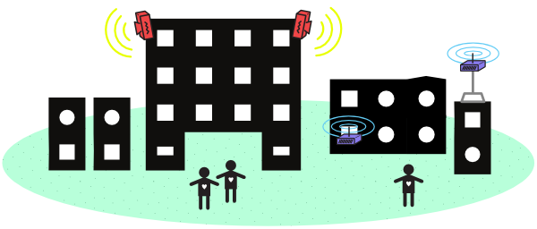
Access Point - Home or Office network
Wireless networks used in your home or office are generally a combination of a router and a wireless Access Point (AP).
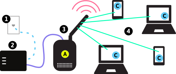
In the diagram above:
- 1 represents the connection to the Internet (Optional - networks can function without the Internet).
- 2 represents the router that assigns IP addresses and provides a firewall between your network and the Internet.
- 3 represents the Access Point, providing a wireless bridge between the router and the users’ devices.
- 4 represent user devices, such as laptops, tablets, and smartphones.
In many home networks, or small office networks, the router and AP may be combined into a single device. This is usually just called a wireless router. It may also have a DSL, Cable, 3G, or 4G port to provide the connection to the Internet. In large office scenarios, there may be several AP devices spread throughout the building to provide more even wireless coverage, connected back to the router through long Ethernet cables.
Point to Point link - Long Distance Connections
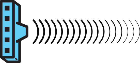
Wireless networks can be used to connect distant buildings or areas. It usually requires very focused antennas - such as a dish antenna - that can send a narrow beam in a specific direction. This is discussed in Learn Wireless Basics - so go there for more details on how that works.
A long-distance connection is often called a “point-to-point”, or “PtP” link. The name describes the concept: two points are connected together, and nothing else. This requires two wireless devices: one configured as an Access Point; the other configured as a Client. In the example below, two wireless devices are configured to create a point-to-point link.
Omnidirectional Access Point and Client Link
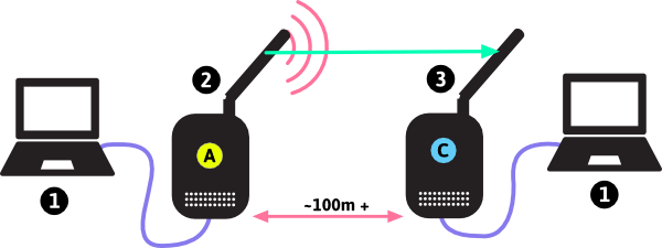
- 1 represents computers connected with Ethernet cables to the wireless devices. These computers are connected to each other over the Point-to-Point link.
- 2 represents the wireless device setup as an Access Point.
- 3 represents the wireless device setup as a Client, connected to the Access Point.
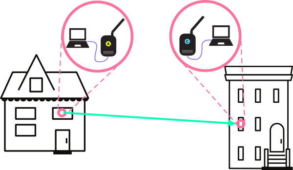
This could look like the building-to-building connection, as shown below:
Long-distance directional Access Point and Client Link
Here we have another example of a point-to-point link, but where the routers have dish antennas for greater link distance.
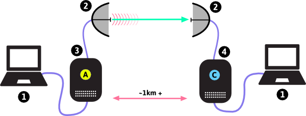
In the diagram above:
- 1 represents computers connected with Ethernet cables to the wireless devices. These computers are connected to each other over the Point-to-Point link.
- 2 represents the wireless device setup as an Access Point.
- 3 represents dish antennas that focus the wireless signal, allowing connections over long distances.
- 4 represents the wireless device setup as a Client, connected to the Access Point.
This could look like the network below, where an AP mounted on a tower is able to connect with a Client device in a home very far away, since the dishes are facing one another.
In both of these examples, there are just two wireless devices linked together - and the antennas determine the range at which they can connect. The more focused the signal, the further the point-to-point link can reach. As the distance between the devices grow, it is more an more important to focus the signal with antennas - at both ends of the connection. Otherwise one end may hear the other, but not be loud enough to be heard!
Point to MultiPoint - Wireless Internet Service Provider model
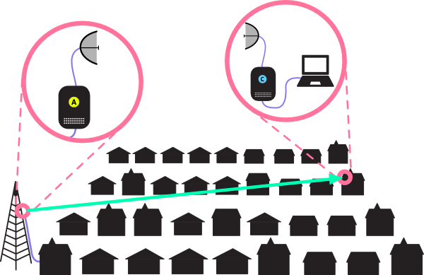
If we combine the two principles used in the networks above - many client devices connecting to an Access Point, and more powerful antennas used for outdoor devices to create longer links - we can create Point to Multipoint networks. These are larger-scale Access Point networks, where there is a single device in the “center”, controlling all of the Clients connected to it and bridging those connections to the Internet.
These types of networks are used by Wireless Internet Service Providers (WISPs) to connect homes and businesses to the Internet. Instead of running cables around a neighborhood or town, they put up one or more powerful Access Points on a tall building or tower. By installing directional wireless devices in a Client role on other rooftops, and pointing them back at the tall building or tower, those buildings can be connected to the WISP’s networks, and thereby the Internet.
The diagram below demonstrates one model for how this works. There is a powerful Access Point mounted on a high building, and several nearby buildings with rooftop wireless Client devices: this forms the Point-to-Multipoint network. Connected to each of the Client devices is an indoor router or Access Point, which allows users to connect their computers, laptops, tablets, or smartphones to the WISP network.
In the diagram above:
- 1 represents the connection to the Internet.
- 2 represents an Access Point providing the signal for Client devices to connect to.
- 3 represents a powerful omnidirectional (all directions) antenna, sending the wireless signal to a large area around the building.
- 4 represent Client wireless devices on the roof of other buildings, linking to the powerful Access Point, and able to connect to the Internet through that AP.
- 5 represents small Access Points distributing wireless service inside the building.
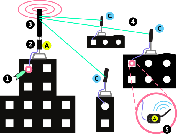
Mesh - Neighbor-to-neighbor Networks
A mesh network takes the principle of Point-to-Multipoint, and extends it to the idea of every node connecting to every other node in range. In effect, this creates a “Multipoint-to-Multipoint” network. This requires that all the devices are in the Ad-Hoc mode - wireless devices all in AP mode or Client mode can’t perform the same function. For more information on how this principle works, see the Introduction to Mesh document.
The diagram below demonstrates one model for how this works. Wireless mesh nodes are installed on the rooftops of various buildings, and those nodes that are in range and don’t have anything blocking the signals will connect. These nodes will share all resources connected to them such as local servers hosting applications and connections to the Internet. They can also be connected to computers, Access Points, or routers inside the buildings so users can access the resources anywhere on the network.
In the diagram above:
- 1 represents the connection to the Internet.
- 2 represents a Mesh Node with a connection to the Internet, with an omnidirectional (all directions) antenna.
- 3 represents Mesh Nodes with omnidirectional (all directions) antennas. These nodes are receiving Internet access from Mesh Node 2. They may be connected to different devices inside the building.
- 4 represents small Access Points distributing wireless service inside the building.
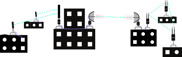
Hybrid Networks
When designing and building town or community-sized networks, it may be difficult or impossible to use a single method to connect everyone. For instance, a single Point-to-Multipoint network may not cover an entire community. Mesh nodes can be used to extend client sites to nearby buildings. Point-to-point connections can bridge longer distances and join several disconnected networks together.
In the diagram below, we can see an example of a hybrid network. There is no single example that can cover all of the possible uses for a network! In the activity that follows, you will explore the different ways to build a network by working through scenarios.
One last note before we move on to the activity - in the examples above, and in the activity that follows, the diagrams focus on building networks across rooftops or from building to building. This is generally the best way to build networks that cover neighborhoods, towns, or communities. In the diagrams, the way people connect to this network isn’t always shown.
Keep in mind that these rooftop routers may not provide connections to users on the ground, or in buildings. A good way to provide these connections is by attaching Access Points to an Ethernet port on the rooftop router. This indoor Access Point can be set up to use the rooftop network as the source of connections to the Internet, or to provide access to applications and servers on the network. A detailed look at this is below:
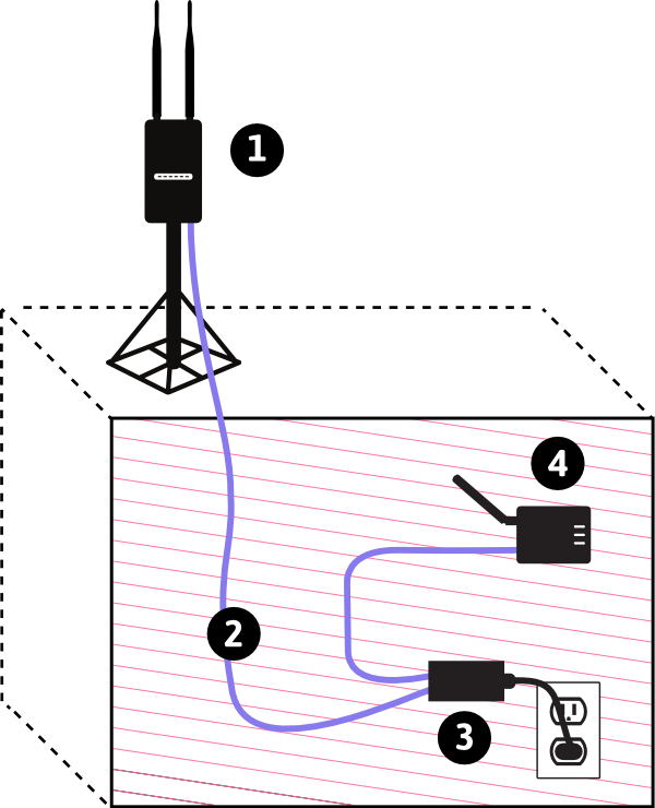
In the diagram:
- 1 represents the rooftop wireless device. It could be a Mesh Node, or Client router.
- 2 represents the Ethernet cable running out to the rooftop from the Power over Ethernet adapter.
- 3 represents a Power over Ethernet (PoE) adapter - a common way to power outdoor wireless devices.
- 4 represents an Access Point, connected to the neighborhood or community network through the rooftop router.
Group Activity
Since there are so many ways to build wireless networks to cover your town or community, we recommend working through these pen-and-paper activities. Download the network worksheets and example solutions and try your hand at designing wireless networks.
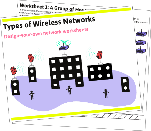
- If you are working through the activity on your own, try printing out the worksheets first and draw in a possible solution to each of the scenarios. You can then review the example solutions and see how your networks compare with some others.
- We recommend you work through this activity with a group of your community members, especially when planning and designing a network. First print out a few sets of the network worksheets, and break into groups of two or three people (depending on how many people are gathered). Draw solutions to each scenario, then meet back up and compare all of your solutions to the scenarios. You can also look through the example solutions and compare them to what your groups came up with. Discuss what solutions might be best for your community.
There are a few basic rules to follow when working through the activity.
1. There are three types of routers you will use:
- Omnidirectional. These can send and receive wireless signals in every direction.
- Sector. These send and receive wireless signals in a limited arc. Limit the connections these routers make to a wedge-shaped area.
- Focused. These send and receive wireless signals in a narrow beam. Limit the connections to a single thin line.
2. You have a limited amount of equipment available for each network. Each worksheet has icons of the types and number of pieces of equipment. The example below provides three omnidirectional, one sector, and one focused router:

3. You can “configure” the wireless equipment in your network to serve any of the wireless roles - AP, client, or ad-hoc node (mesh). The equipment can be any combination of roles, they don’t have to all be the same role. Label each router with an “A”, “C”, or “M” depending on the role.

4. You can assume that all of the wireless equipment in the examples are within range of each other - the signals will reach.

5. Remember that Clients can only connect to Access Points. APs cannot connect to each other wirelessly, Clients cannot connect to each other wirelessly, and Mesh nodes cannot connect to APs or Clients wirelessly.
6. Many Clients can connect to a single Access Point. Ad-hoc (mesh) devices can have connections to multiple other mesh devices at once.

7. If you want to connect different combinations of devices together, you can “wire” them together, as if you plugged an Ethernet cable in between the devices. This way devices that normally cannot connect wirelessly can still be networked. For example, an Access Point or Client can be connected to a Mesh node with an Ethernet cable.

Now download and print out the worksheets and example solutions, and try out some designs!
</section>Definitions
- Ad-hoc Network / Device Network
- On some devices (e.g. laptops) some available network connections are shown as computer to computer networks. These are networks that may be ad-hoc mesh networks or point to point links between computers for small file sharing. The term “ad-hoc” can also refer to unplanned, decentralized network connections.
- Antenna
- Converts electrical signals to radio waves. It is normally connected to a radio transmitter or radio receiver, and is the interface between the electrical signals in the radio, and the movement of the signals through the air.
- AP (Access Point)
- A device that allows wireless devices to connect to a wired network using Wi-Fi or related standards Client Device : The device with a wifi radio that you use to connect to a wireless access point, e.g. a computer, cell phone or tablet device.
- Ethernet
- A type of networking protocol - it defines the types of cables and connections that are used to wire computers, switches, and routers together. Most often Ethernet cabling is Category 5 or 6, made up of twisted pair wiring similar to phone cables.
- PoE (Power over Ethernet)
- describes systems which pass electrical power along with data on Ethernet cabling.
- Node
- An individual device in a mesh network.