Introduction
When planning and building a network, you will need to install the wireless routers (or nodes) that make the most sense for each site. In most cases, a single wireless router on a rooftop or in a window will connect to nearby neighbors and form a mesh. In some cases, this wireless node may be connected by Ethernet cable to a gateway connection to the Internet, sharing it with those neighbors. In other cases, the node will be connected by Ethernet cable to one or more computers inside the building, some of which may be sharing local applications.
The instructions below are designed to show you examples of how to set up the hardware in different ways. Each configuration listed below describes the settings you should change to make the network work according to your plans. These setup examples are based on the recommendations in Guidelines for Mesh Networks.
Basic Setups
Two or more nodes meshing wirelessly
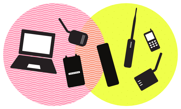
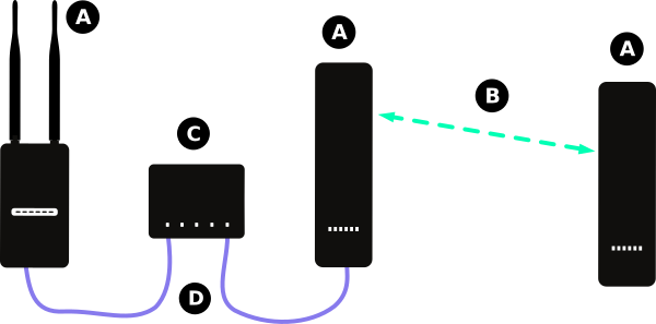
The most common configuration of wireless nodes is made up of the nodes themselves, the mesh links between nodes, and any users connected to the network. It involves two or more wireless nodes, installed with a mesh firmware. The nodes in the example below are an assortment of omnidirectional nodes, but the specific type doesn’t matter as long as they are within wireless range of each other.
In the diagram above:
- (A) Represents wireless nodes running a mesh firmware.
- (B) Represents the wireless mesh links between the nodes.
The configuration of each type of mesh firmware will be different, but this setup should work with all versions. As long as there are not obstructions between the wireless devices, and the devices are within range, they should connect and form a single network.
One or more nodes connected to a gateway
Most networks are designed to provide services, with a connection to the global Internet being the most popular! Most mesh firmware is designed to share services across the entire mesh network by default, and will attempt to detect a gateway connection to the Internet when the routers boot up. If the wireless router receives an IP address via DHCP on the wired Ethernet port, it will set itself up as a gateway.
In the diagram above:
- (A) Represents the nodes running mesh firmware.
- (B) Represents the wireless mesh links between the nodes.
- (C) Represents the connection to the Internet.
- (D) Represents the modem or router from the Internet Service Provider (ISP), connected to the Internet. It provides IP addresses on the local port with DHCP.
The type of modem will vary depending on the Internet Service provider, but it should have at least two ports:
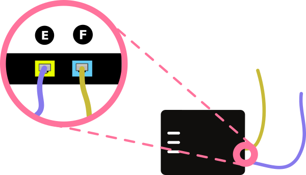
- (E) Shows the modem LAN port, which is connected to the router’s WAN port. There may be multiple LAN ports on the gateway modem, any should work fine.
- (F) Shows the modem connection to the Internet - via DSL, cable, 3G USB adapter, or other type.
The cable from the modem LAN port should run to the WAN port on the mesh router. On most outdoor routers, there will be a single port on the unit’s PoE power supply. On routers with multiple ports, the WAN port will typically be labeled, and is often a different color - usually blue. These examples are shown below:
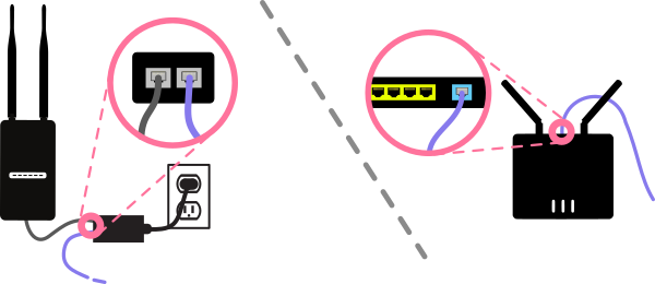
The mesh router node connected to the modem should receive an IP address and configure itself as a gateway. It will advertise this on the network by default. At this point, the user connecting to the mesh node should be able to access the Internet.
Node connected to a local application server
You have a web server hosting a community blog on your computer, and you want to share it with the neighborhood network. Connect the computer to the mesh node using the wired Ethernet port. The laptop will receive an IP address on the mesh, and you can access the server on the mesh by entering it’s IP address or domain name into your web browser’s URL bar. On some mesh firmware, such as Commotion - there is an application portal where advertised applications can be found. If you are using Commotion, you can add the server information on the attached node, and that will be advertised to users on the mesh via the splash page on all of the nodes with a good connection.
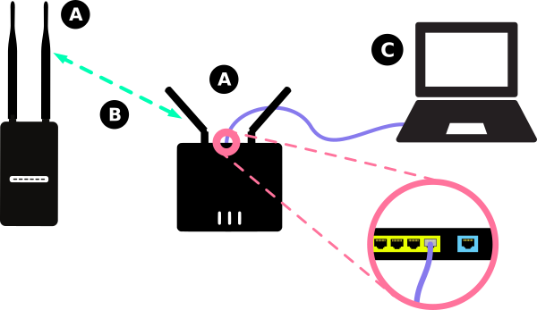
In the diagram above:
- (A) Represents a node running mesh firmware.
- (B) Represents the wireless mesh links between the nodes.
- (C) Represents a laptop set up as a server, connected to a node’s wired Ethernet port. In this case, one of the LAN ports.
The cable will run from the mesh router’s LAN port. On most outdoor routers, there will be a single port on the unit’s PoE power supply. On routers with multiple ports, the LAN ports will typically be labeled, and are often a different color - usually yellow. These examples are shown below:
Node connected to an external AP or router
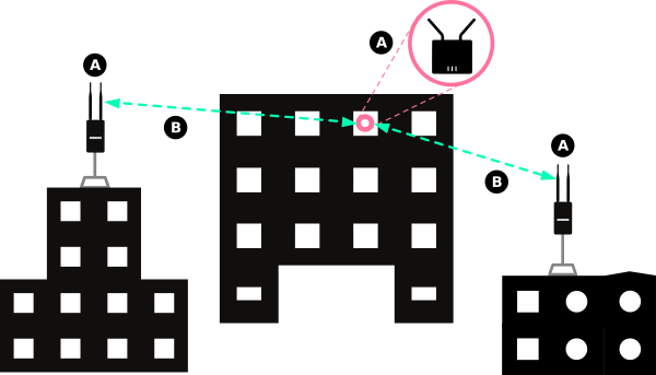
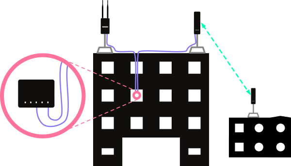
If there is no Internet connection inside a building, but it is available elsewhere in the mesh, you can connect to the rooftop mesh network to provide access. Connect an indoor Access Point or router with a wireless AP to the wired Ethernet port of the mesh node on the roof. The node will provide any users connecting to the AP with wireless devices such as smartphones and laptops with IP addresses on the mesh. These non-mesh routers and Access Points can add wireless coverage to areas not covered by the outdoor mesh nodes. By connecting to these indoor APs, users can access the services and gateways that are on the mesh. Since mesh firmware isn’t compatible with every router, this method allows you to use routers and Access Points you might already have.
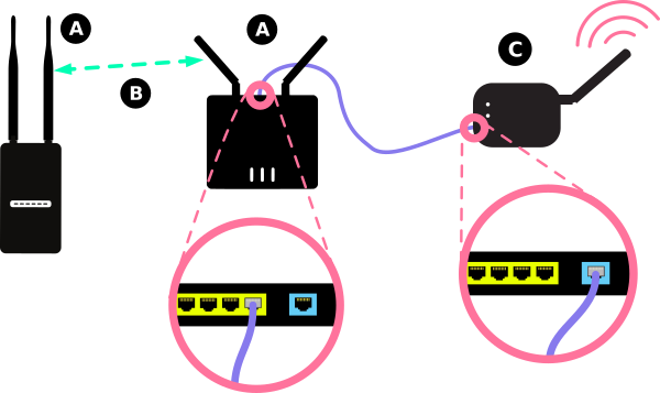
In the diagram above:
- (A) Represents the nodes running mesh firmware.
- (B) Represents the wireless mesh links between the nodes.
- (C) Represents an external Access Point or router, not running mesh firmware. This is connected to the second node’s wired Ethernet LAN port.
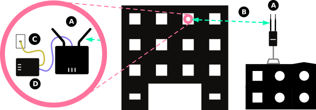
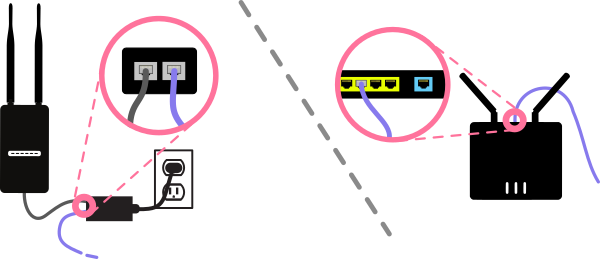
The diagram below demonstrates what this would look like with equipment installed on a building:
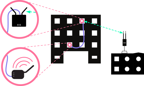
Most mesh firmware should support this option. If there are LAN ports on the device, or they can be configured to hand out IP addresses with DHCP, an Access Point will “pass through” requests from wireless devices to the mesh router. This way you can extend the capacity of the mesh router to areas of a building, and not use wireless bandwidth or cause interference.
Advanced Setups
For most community wireless networks, the simple setups above will fit the needs of the neighborhood or town. For others, more complex installations and configurations will be required. The hardware setups below involve more complicated arrangements of routers, when there is a need to connect multiple nodes together at a single site. Some of the instructions below require some familiarity with networking concepts, so we recommend reading through Learn Networking Basics first.
Each of these setups show the configuration of mesh nodes to connect with Ethernet. Whenever possible, using wired Ethernet connections can greatly speed up your community network. There is much more bandwidth available with wired links, and there will be no interference when using cables. For more information on increasing performance on your community network, see Guidelines for Mesh Networks.
Mesh with Ethernet with DHCP
Using a gateway to the Internet with DHCP for automatic assignment of IP addresses
If you want to provide a gateway connection to the Internet on your mesh network, it helps to use several nodes at the location hosting that connection. This should reduce bottlenecks that would occur if there were only one node connected to that gateway.
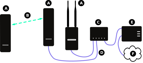
In the diagram above:
- (A) Represents a node running mesh firmware.
- (B) Represents the wireless mesh links between the nodes.
- (C) Represents an Ethernet switch, which transfers data between all connected devices.
- (D) Represents Ethernet cabling connecting the modem and nodes to the Ethernet switch.
- (E) Represents the modem or router from the Internet Service Provider (ISP), connected to the Internet. It provides IP addresses on the local port with DHCP.
- (F) Represents the Internet.
The diagram below demonstrates what this would look like with equipment installed on a building:
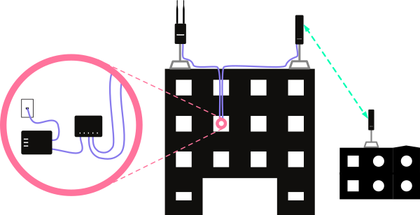
The steps to configure this functionality will be different for every mesh firmware. For routers running Commotion, see the Advanced Hardware Setups guide. For routers running LibreMesh, if all of the routers are connected via the LAN ports, they should mesh automatically over Ethernet and form a mesh. For other firmware, consult the documentation.
Tip: Mounting wireless routers very close to each other can cause interference. For best performance, we recommend mounting equipment on separate poles, with two or three meters (6 to 10 feet) between them and using metal shields on the back of directional nodes. These reduce the wireless signal radiated from the back of the equipment, reducing the interference. You can buy these commercially, or make your own from metal building studs.
Mesh with Ethernet with Static addressing
Static IP addresses, without a Gateway to the Internet
Even if a tall or centrally located site doesn’t have a gateway to the Internet, it may help to mount several wireless nodes there to act as a “supernode” on the network. This can increase throughput on the network and reduce bottlenecks for very busy nodes or nodes with many, many connections on the mesh.
In the diagram above:
- (A) Represents a node running a mesh firmware.
- (B) Represents the wireless mesh links between the nodes.
- (C) Represents an Ethernet switch, which transfers data between all connected devices.
- (D) Represents Ethernet cabling connecting the modem and nodes to the Ethernet switch.
The diagram below demonstrates what this would look like with equipment installed on a building:
The steps to configure this functionality will be different for every mesh firmware. For routers running Commotion, see the Advanced Hardware Setups guide. For routers running LibreMesh, if all of the routers are connected via the LAN ports, they should mesh automatically over Ethernet and form a mesh. For other firmware, consult the documentation.
Tip: Mounting wireless routers very close to each other can cause interference. For best performance, we recommend mounting equipment on separate poles, with two or three meters (6 to 10 feet) between them and using metal shields on the back of directional nodes. These reduce the wireless signal radiated from the back of the equipment, reducing the interference. You can buy these commercially, or make your own from metal building studs.
Mesh with Ethernet with a Static Gateway
Using Static IP addressing, with a Gateway to the Internet
This example is similar to the other example with a gateway above, but the gateway to the Internet does not provide IP addresses automatically using DHCP. You must configure the addresses for your mesh nodes manually. In this example the gateway IP address is 192.168.50.1, but you will need to obtain the proper IP address information from your Internet service provider.
In the diagram above:
- (A) Represents a node running a mesh firmware.
- (B) Represents the wireless mesh links between the nodes.
- (C) Represents an Ethernet switch, which transfers data between all connected devices.
- (D) Represents Ethernet cabling connecting the modem and nodes to the Ethernet switch.
- (E) Represents the modem or router from the Internet Service Provider (ISP), connected to the Internet. It is configured with a Static IP address, and does not provide IP addresses to clients automatically via DHCP.
- (F) Represents the Internet.
The diagram below demonstrates what this would look like with equipment installed on a building:
The steps to configure this functionality will be different for every mesh firmware. For routers running Commotion, see the Advanced Hardware Setups guide. For routers running LibreMesh, if all of the routers are connected via the LAN ports, they should mesh automatically over Ethernet and form a mesh. For other firmware, consult the documentation.
Tip: Mounting wireless routers very close to each other can cause interference. For best performance, we recommend mounting equipment on separate poles, with two or three meters (6 to 10 feet) between them and using metal shields on the back of directional nodes. These reduce the wireless signal radiated from the back of the equipment, reducing the interference. You can buy these commercially, or make your own from metal building studs.
Conclusion
These hardware setup examples should provide you with some ideas on where and how to set up your wireless routers when building your community network. For more information and ideas, please see the rest of the Neighborhood Network Construction Kit.
Definitions
AP (Access Point) - A device that allows wireless devices to connect to a wired network using Wi-Fi or related standards.
DHCP: Dynamic Host Configuration Protocol - It assigns IP addresses to client devices, such as desktop computers, laptops, and phones, when they are plugged into Ethernet or connect to Wireless networks.
Ethernet - A type of networking protocol - it defines the types of cables and connections that are used to wire computers, switches, and routers together. Most often Ethernet cabling is Category 5 or 6, made up of twisted pair wiring similar to phone cables.
Router - A device that determines how messages move through a computer network.
Node - An individual device in a mesh network.
WAN: Wide Area Network - Signifies the connection to the global Internet or a different, typically larger, network.